DINEX Multi-Function Display 3

MFD3 IDE software can be used to customize the MFD3. Customizable items include telltales, gauges, J1939 SPN items, and J1939 heartbeats. For example, a telltale icon can be changed from one graphic file to another graphic file. A DEF gauge can be changed to a SOC gauge. One J1939 SPN item can be changed from CNG tank pressure to fuel level. J1939 heartbeats of a CAN device’s source address can be easily changed to a different source address. The twelve LED warning lights are designed to comply with FMVSS for critical information such as Stop Engine, Check Transmission, and Directional Signal indicators. The OEM will specify which items must have a warning light on the MFD3. Other functions are shown on the LCD screen. For example, the LCD display can show 8 gauges and 35 telltale positions. The actual LCD display is programmable and may be optimized for each vehicle application. The analog style gauges may display information such as SOC, range, coolant temperature, oil temperature, oil pressure, air pressure, etc. The display information comes directly from the Powertrain J1939 interface and any additional CAN data buses available on the vehicle. The MFD3 can handle up to 4 video camera inputs and one HDMI input. When the vehicle is in reverse, the MFD3 will display a view from the rear camera as though the MFD3 is a rear view mirror. When a passenger door is enabled, the MFD3 will show a view from a door camera, which will give the operator a view of the passenger door as the passengers exit the bus. The operator will know if there is an obstruction in the door viewed by the MFD3. In maintenance mode, the MFD can display the DIO module input/output status and output load current plus display the multiplex system ladder logic in real time (RTLM). The LCD display can also show available J1939 Powertrain information, such as Engine, Transmission, Traction (electric drive), and ABS/Traction Control Device in real time. The display items represent a practical list of useful data items. Available J1939 data is dependent on the subsystems manufacturer’s willingness to provide the data.
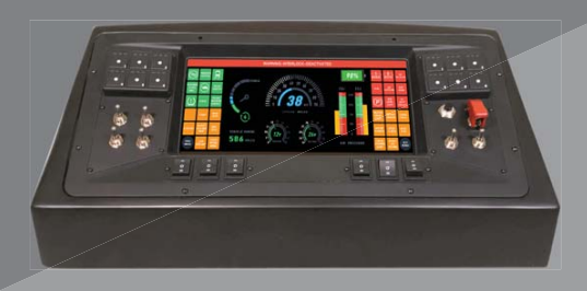
The I/O Controls Multi-function Display 3 (MFD3) is a complete on-board computer system with a Linux OS. The large color 12.3” 1920*720 LCD touchscreen will display safety related information or operational information in large, easy to read graphics. The twelve LED warning lights are programmable, and may serve any annunciation or alarm function. The MFD3 will display information about the Powertrain J1939, secondary CAN and DINEX multiplex system. It has both driving mode and maintenance mode. The driving mode is intended to provide useful information during vehicle operation. The maintenance mode is used for vehicle trouble-shooting or service.
Unique features of the MFD3 are Over-The-Air (OTA) download/upload, remote diagnostics, on demand data download and HDMI video input. With OTA capability MFD and MBC programs may be automatically updated from a remote PC. The patent pending OTA feature includes security tokens and geo fence restrictions so MFD and MBC programs may only be updated under certain conditions set by the OEM / TA. The MFD3 also includes the capability for remote diagnostics that diagnose issues with the vehicle. Whether remotely or while onboard the vehicle all multiplex and J1939 data is available via the MFD3 for review and use while diagnosing vehicle issues. Also available on board the vehicle for view in real time on the large 12.3” display is the multiplex system ladder logic diagrams. Additional MFD3 capabilities are on demand data download. From any remote PC with an internet connection the user can specify what multiplex and/or J1939 data to download for a specified amount of time (5 minutes, 10 minutes, etc.).


Unique Features
• 12.3” LCD Touchscreen Display with high contrast (1100) and high luminance (1000 cd/ m2)
• 1920 * 720 Display Resolution
• Over-The-Air (OTA) Download / Upload Program Updates
• Remote Diagnostics Capability
• On Demand Data Logging Capability
• Displays 8 Unique Gauges
• Informational Driver Mode
• Diagnostic Maintenance Mode
• Displays Multiplex System Information
• Displays J1939 Power Train And Vehicle Subsystem Information
Specification LCD: • 12.3” TFT 1920 * 720 Color LCD touchscreen display • Luminance 1000 cd/m2 • Contrast 1100 Telltale LED: • 12 Position Telltale LED Programmable LCD Display: • 8 Gauges & 35 Telltale LED Video Input: • 4 Video Inputs (2-NTSC, 2-AHD NTSC) • 1 HDMI Input Other Interfaces: • DINEX CAN Port • J1939 Port • Secondary CAN Port Multiplex Communication: • CAN Bus Communication Protocol • 250/500 Kbps Communication Rate
Power Requirement: • 9-36 VDC Dimensions: • 14.13”(W) x 6.88”(L) x 2.38” (D) • 359mm (W) x 175mm (L) x 61mm (D) Weight: • 3.1 LBS Operating Temperature: • -20C ~ +70C (LCD Touchscreen Operating Range) Requirements: • OTA features require Ethernet connection to vehicle’s onboard router